
THT TYPE INTERFACE UNIT
FEATURES
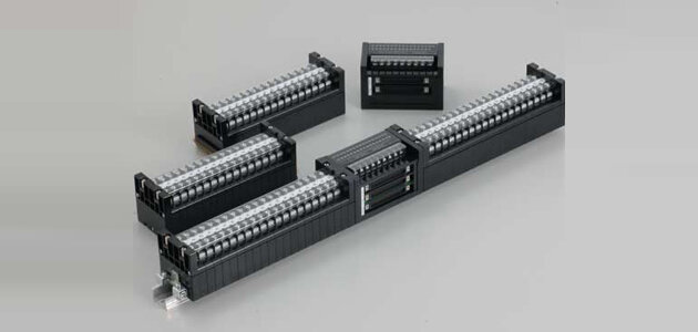
THT-type interface units share the same DI/DO unit configuration. This gives both models a sleek appearance. Furthermore, the connector and operation display are laid out in the center of the unit, and DI/DO are placed 16 bits each on the left and right. Terminal block sections located on both the left and right sides allow separation of the upper and lower sections, allowing the main unit to be replaced without removing the wiring. TJ-5.5 type test connectors can be mounted on terminal blocks.
Interface unit with built-in DI module
The photocoupler module is built into the external terminal block (screw size M4) and converts 110 VDC to 24 VDC simply by wiring to the terminal block. The internal photocoupler module provides insulation to minimize external surges entering the panel (improved noise performance).
Interface unit with built-in DO module.
A contact relay is built into the outside wire terminal block (screw size M4) to control a 110V DC circuit with a signal (24V DC) from a sequencer. This eliminates the need for relay terminal blocks, which were previously required, and reduces the number of parts mounted in the panel and wiring man-hours significantly. The number of mounted parts and wiring man-hours in the panel can be significantly reduced by eliminating the need for relay terminal blocks that were previously required.
| Item | THT-34X091【DI TERMINAL BLOCK】 | |||
|---|---|---|---|---|
|
Normal service condition |
Operating temperature | -10to55℃ | no freeze / no condensation | |
| Storing temperature | -20to60℃ | |||
| Relative humidity | 20to80% | |||
| Altitude | 2,000m以下 | |||
| Rating | Input | Circuit voltage | DC100/110V(DC80~143V) | |
|
Rated current-carrying capacity (Ith) |
About 1.6mA (at 110V DC and when inrush, allowable voltage is about 20mA.) | |||
| Input Impedance | About 68kΩ (110V DC) | |||
| Operating characteristics | Non-operation under 60V DC, complete operation over 80V DC. | |||
| Output | Circuit voltage | 24V DC (Max. allowablw voltage is 30V DC) | ||
|
Leakage current when circuit open |
20μA or less | |||
| Rated load current | 5mA or less | |||
| Set time | 150μs or less | |||
| Reset time | 5ms or less | |||
| Performance | Insulated resistance | Between all circuit and ground | 10MΩ or more (500V DC mega) | |
| Between I/O Circuit | 5MΩ or more (500V DC mega) | |||
|
Power frequency
withstand voltage |
Between input circuit and ground | 2,000V AC (60MHz) 1/min | ||
| Between output circuit and ground | 500V AC (60MHz) 1/min | |||
| Between I/O Circuit | 2,000V AC (60MHz) 1/min | |||
|
Impulse withstand voltage (Uimp) |
Between input circuit and ground (includes output circuit) | ±7kV (1.2×50 each 3 time μs) | ||
| Oscillatory surge voltage | Between input circuit and ground |
First wave height: 2.5 to 3kV Vibration frequency: 1.0 to 1.5MHz 1/2 damping time: 6μs or more Repetition frequency: More than 50 times/s/s Output impedance of circuit: 150 to 200Ω or more for 2 sec. |
||
| Between input circuit terminals | ||||
| Square wave impulse noise | Between input circuit and ground |
Voltage (Vp): 1kV±10% Polarity: positive and negative Output: coaxial Dynamic output impedance: 50Ω Rise time (Tr): 1ns±30% Pulse width (Tw): 100ns±30% Repetitive frequency: More than 50/60Hz or more for 2 sec. |
||
| Between input circuit terminals | ||||
| Electric wave noise | Radio irradiation of 150,400 and 900 MHz bands | |||
| Electrostatic discharge noise |
Contact discharge: 8kV Air discharge: 4kV Cathode only (10 times or more) |
|||
| Vibration resistance | Acceleration: 9.8m/s2、Direction: Forward / backward, right / left, up / down, Vibration time: 1800s | |||
| Shock resistance | 294m/s2(6 directions, 3 times / each) | |||
THT-34X092【DO TERMINAL BLOCK】
| Item | THT-34X092【DI TERMINAL BLOCK】 | ||||
|---|---|---|---|---|---|
|
Normal service condition |
Operating temperature | -10to55℃ | no freeze / no condensation | ||
| Storing temperature | -20to60℃ | ||||
| Relative humidity | 20to80% | ||||
| Altitude | 2,000m or less | ||||
| Rating | Coil | Coil voltage | 24V DC±10% | ||
| Current consumption | 12.5mA (Rated input) | ||||
| Coil resistance | 1920Ω | ||||
| Set time | 10ms or less | ||||
| Reset time | 10ms or less | ||||
| Output | CN | Circuit voltage | DC24V | ||
|
Circuit current -carrying capacity |
10mA(1Pin) | ||||
| Terminal | Circuit voltage | 100/110V DC or 24V DC | |||
|
Circuit current -carrying capacity |
Max. 5A | ||||
| Performance | Insulated resistance | Between all circuit and ground | 10MΩ or more (500V DC mega) | ||
|
Between terminal side output contact and CN side output contact and coil circuit |
5MΩ or more (500V DC mega) | ||||
| Power frequency withstand voltage | Between all terminal side output contact and ground | 2,000V AC (60MHz) 1/min | |||
| Between output contact of CN side, coil circuit and ground | 500V AC (60MHz) 1/min | ||||
|
Between terminal side output contact and CN side output contact, coil circuit |
2,000V AC (60MHz) 1/min | ||||
| Impulse withstand voltage (Uimp) |
Between terminal side output contact and ground (includes CN side output contact and coil circuit) |
±4.5kV (1.2×50each 3 time μs) | |||
| Oscillatory surge voltage | Between terminal side output circuit and ground |
First wave height: 2.5 to 3kV Vibration frequency: 1.0 to 1.5MHz 1/2 damping time: 6μs or more Repetition frequency: More than 50 times/s Output impedance of circuit: 150 to 200Ω or more for 2 sec. |
|||
| Between terminal side output circuit terminals | |||||
| Square wave impulse noise | Between terminal side output circuit and ground |
Voltage (Vp): 1kV±10% Polarity: positive and negative Output: coaxial Dynamic output impedance : 50Ω Rise time (Tr): 1ns±30% Pulse width (Tw): 100ns±30% Repetitive frequency: More than 50/60Hz or more for 2 sec. | |||
| Between terminal side output circuit terminals | |||||
| Electric wave noise | Radio irradiation of 150,400 and 900 MHz bands | ||||
| Electrostatic discharge noise |
Contact discharge: 8kV Air discharge: 4kV Cathode only (10 times or more) |
||||
| Vibration resistance | Acceleration: 9.8m/s2, Direction: Forward / backward, right / left, up / down, Vibration time: 1800s | ||||
| Shock resistance | 294m/s2(6 directions, 3 times / each) | ||||
| product | document | data type | volume of data | date of update | download |
|---|---|---|---|---|---|
| THT TYPE INTERFACE UNIT | Catalog | 2036.4KB | - | download |
